


Micro USB Breakout Board – Unassembled
The power supply for the motors will be a power bank, a rechargeable battery pack with two USB ports for output. USB cables data cables contain 4 or 5 wires, depending on the connector. The two choices are to either modify an USB cable by cutting off one of the connectors and accessing the wires directly or using some form of adapter. My choice was to use and adapter. What I found to do the job was a Micro USB Breakout Board. This board, technically called a Female MICRO USB to DIP 5-Pin Pinboard by manufacturer, breaks out the wires and makes them available by way of pins. Some assembly is required.
The board comes in two pieces, the board itself and a set of header pins that require soldering. The board arrives as a set of 10 board in two rows of five. It took just a little bit of flexing to break the individual boards apart. The header pins came as longer headers that need to be cut to the correct length. Standard wire diagonal was all that was required to cut the header pins into smaller header pins of 5 pins each.

Micro USB Breakout Board – Assembled
This is the first time that I ever tried to solder header pins onto a board. I was concerned as to how I was going to hold the board and the header pins in place and still have two free hands for soldering. The issue about how to hold the header pins in place turned out to be moot. The header pins held themselves. It was a tight fit placing the shorter pins into the holes on the board and the pins did not move once in place. The holes are visible on the right side of the board though difficult to see in my first photo.
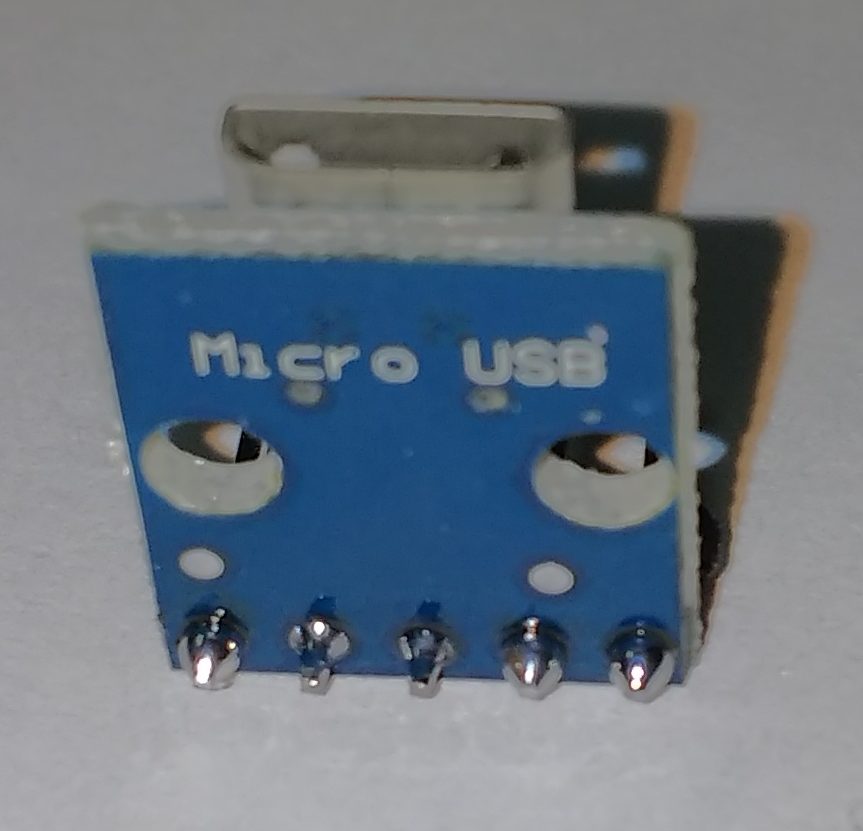
Micro USB Breakout Board – Assembled
A soldering vise was used to hold the board, allowing me to keep my hands free to hold the soldering iron and the solder. The soldering vise has two adjustable arms with clips and a magnifying class. The magnifying glass was not useful to me during the actual soldering. I have not used it enough and had a hard time judging the position of the soldering iron relative to the board. The magnifying glass did allow me to check my work after finishing each solder.
The pins are 2.54 mm apart which provides scale to the photos. My soldering job was not consistent. Two of the pins could probably use more solder. I am only going to be using the outer two pins, ground and VCC. I am not really concerned to how well the three data pins were solder, so long as they do not short out anything.
Two wires will be attached to the ground and voltage pins at one end and screw into the external power connectors on the L293D Motor Driver Board. The L293D board is a shield that sits on top of the Arduino board.