

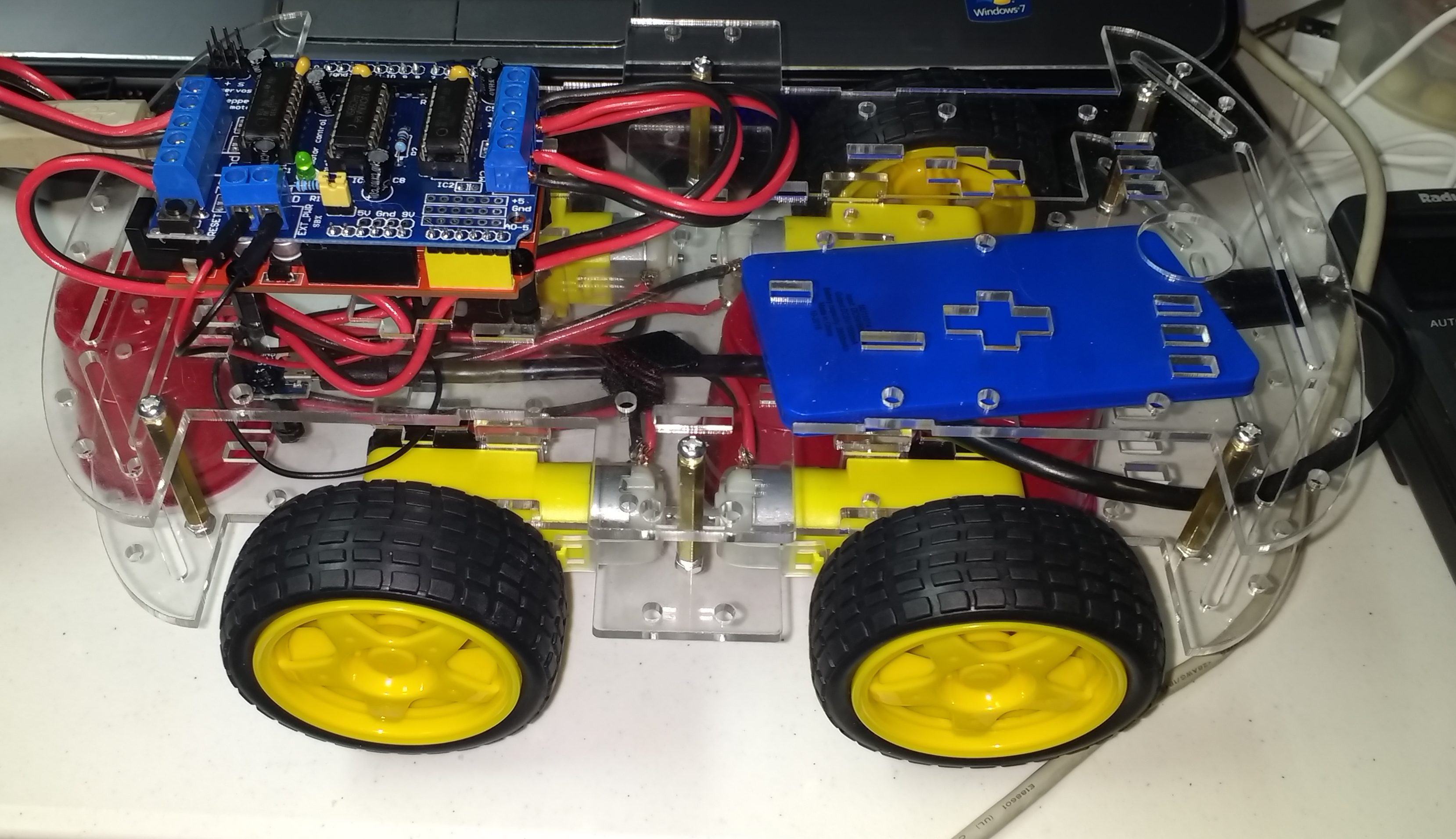
Robotic Car partially assembled.
I have already had to alter my design plans for assembling this robotic car. I wanted to place the Arduino with its Motor Driver Shield between the two platforms. This did not work. The combo Arduino, Motor Driver Shield, and spacers was a few millimeters too tall. With the combo on top of the bottom platform, both sides of the top platform could not be screwed into the brass spaces that separates the two platforms. Plus it turns out that there is only one place on each platform where the spacer holes in the Arduino board lines up with the matching holes in the platform. So, the Arduino has moved to the top platform. By definition, the Arduino is on the back end of the robotic car. And “by definition” means that I could have called either end the front. The front of the car is reserved for the servo motor and the ultrasonic distance finder sensor.
This leaves the issue of where the Raspberry Pi is going to go. I suspect that there are not a set of holes in the platform that will line up with the mounting holes in the Raspberry Pi board. That is a future task. If the Raspberry Pi does not fit, there are two options. One: it could be replaced with a wifi board leaving the Arduino to do all the computation and communications – not the option I want. Two: create a platform that a set of holes that line up with the platform and another set that line up with the Raspberry Pi. Number two is my preferred option. I just have to figure out how to make that mini-platform.
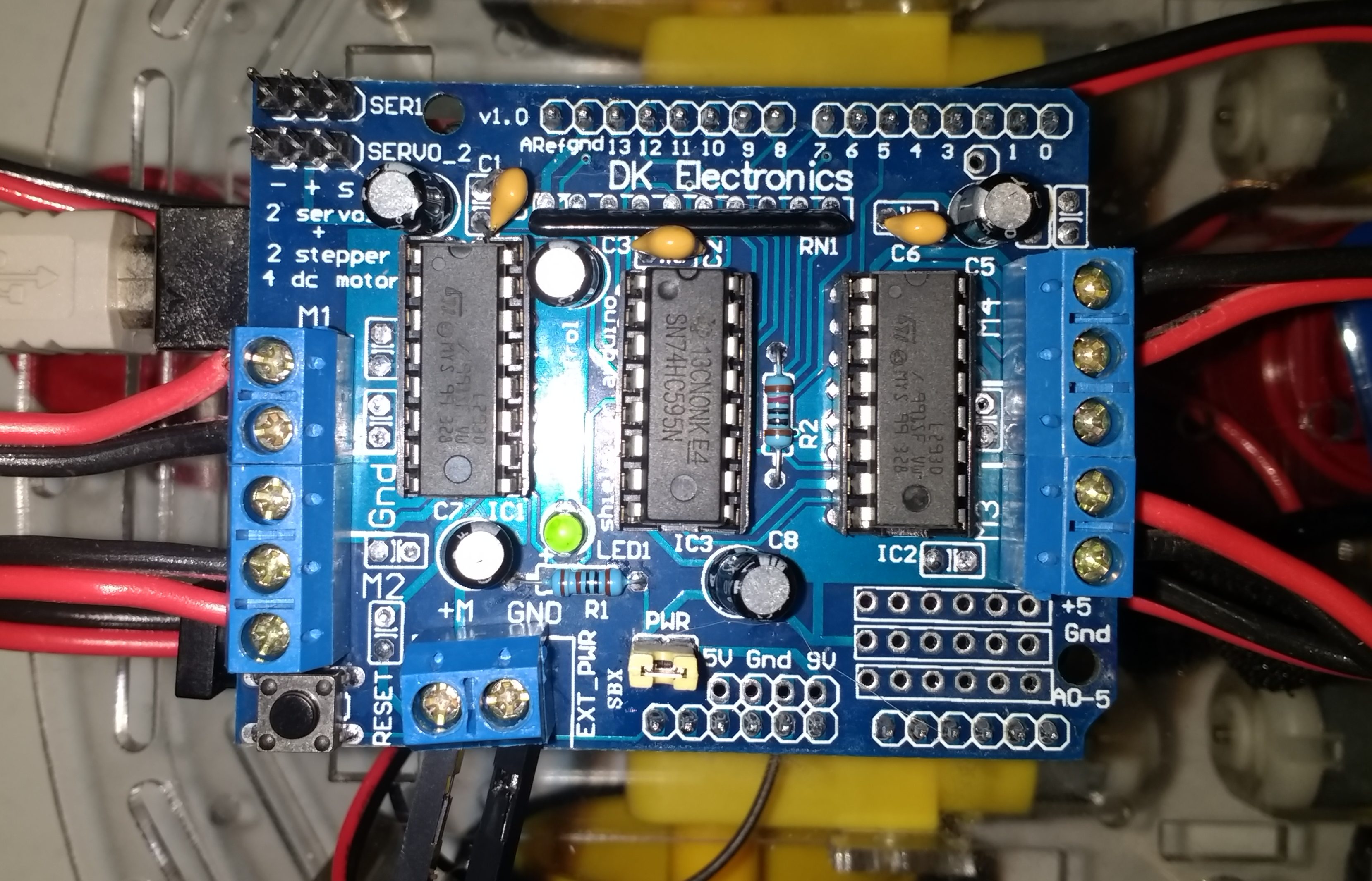
The Motor Driver Shield on the Arduino UNO.
The four DC motors have been wired into the Motor Driver Shield though the connectors M1 to M4. The front wheels are connected to M1 and M2, the blue connector bus on the left side. The rear wheels are connected to M3 and M4, the blue connector bus on the right side. The wheels on the left are connected to M1 and M3 and the wheels on the right to M2 and M4. External power from a USB source is wired into the blue connector on the bottom of board, on the left side.
Initial testing showed that the rear wheels were turning backwards when the command to go forward was executed. This was fixed by reversing the wires going into M3 and M4. The front motors have their red wire connected to the outside of connector block and the real motors have their black wires connected to the outside of the connector block. In hindsight, this makes perfect sense. The rear motors are facing the opposite direction relative to the front motors.
For more information on the Motor Driver Shield for Arduino check out this sellers page,
Multi-Motor Driver Shield (2-L293D)
. This page has links to the AFMotor library that I used. Note, I found this same board elsewhere at a cheaper price.