

Introduction
The StripTease project is an Arduino based project for demonstrating how WS2812B, addressable RGB LED, units can be controlled.
A WS2812B is a unit that contains a red, green, and blue LED and an IC chip for control. To an observer, the unit looks like a single LED that can change colors.
Each unit has four connectors. A VDD for power supply, a VSS for connecting to ground, DIN for Control Data Signal Input, and DOUT for for Control Data Signal Output. Multiple WS2812B units can be strung together by connecting their VDD to a common power supply such as 5V, their VSS to a common ground and the DOUT of one unit to the DIN of the next unit.
The StripTease project started out with just a single strip of 60 WS2812B LEDs. Hence, the name of the project was based on the strip and that it only provided a few ways of using the strip, a tease of sorts. After the project started, a ring of 12 WS2812B was obtain. The ring is just a strip that has been laid out in a circle. It is still a strip with a first and last unit for addressing purposes.
WS2812B & NeoPixel References
-
Addressable RGB LED Controllers
Information about LED units that are controllable and addressable so that they can be strung together into a strip or chain. This includes WS2812B (a.k.a. NeoPixels), SK6812, and APA102C. -
Guide for WS2812B Addressable RBG LED Strip with Arduino
Information on WS2812B LED strips and how to use them with an Arduino. -
How to Control WS2812B Individually Addressable RGB LEDs using Arduino
This tutorial goes over what it takes to use WS2812B RGB LEDs with an Arduino. -
WS2812B Datasheet and Specification
Information about WS2812B controllable RGB LED units. The documentation covers characteristics of a WS2812B LED, how it works, how to control it, and much more.
Hardware List
- Arduino Nano
- WS2812B strip of 60 units
- WS2812B strip of 12 units, can be in the form of a ring.
- two 330 Ω resisters
- one 10k Ω resister
- push button
- breadboard
- MB102 Power Supply Module for Breadboards
- Power Supply — two 18560 4.2V batteries.
An Arduino UNO can be used in place of the Arduino Nano. Any Arduino should work.
The 60 unit WS2812B requires more power than an Arduino can provide, therefore it is necessary to use an external power source. An MB102 Power Supply Module is used in this project. This module takes a range in input voltages and converts them to 5V and/or 3.3V. The power is supplied to the power rails of the breadboard and provides the amperage necessary to power the Arduino and both the WS2812B strips.
Circuit Diagram
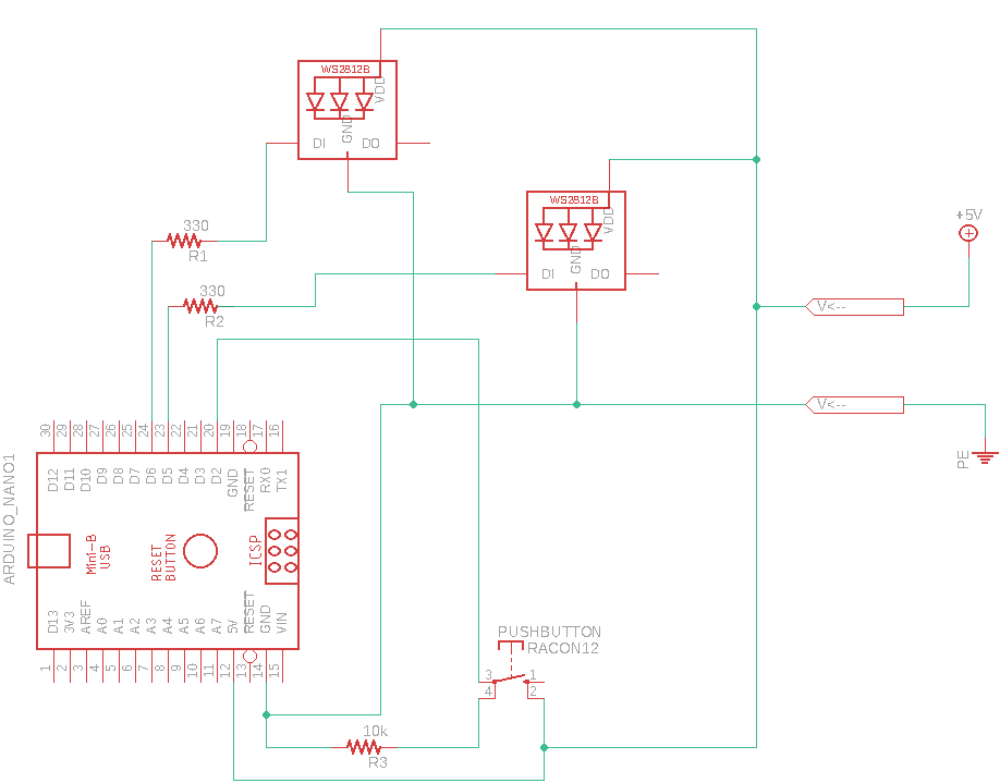
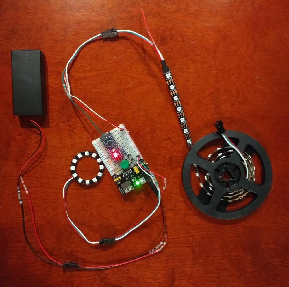
The circuit diagram above is the basic setup of the photo at the top of this page. The MB102 power supply is not explicitly shown and is connected to the +5V and GND lines on the right of the diagram. The WS2812B connected to the D6 pin of the Arduino is the 60 unit strip and the one connected to the D5 pin is for the 12 unit ring. The signal from the closed push button is connected to the D2 pin on the Arduino which is used to trigger interrupts. Changes to which pins are used on the Arduino would require the corresponding changes made to the source code.
Third Party Software
Controlling an string of WS2812B units requires setting up an array of bits, 24 bits for each unit, and sending the bits at the rate that the WS2812B controller can handle. Instead of writing this code from scratch, a third party library was used. This library is FastLED. There was also another contender, it was the Adafruit NeoPixel library. The FastLED library was chosen because it supports different types of Addressable RGB LED units. This includes the WS281x series, NeoPixels, 4 LED units that add a white LED, three and four wire units. The WS2812B and NeoPixels are three LED units, containing red, green, and blue LEDs, and are three wire units. Three wires because only the V+, GND, and Data In are connected to the Arduino. The WS2812B fourth wire, the Data Out, is connected to the next WS2812B unit in the chain.
For more information about the FastLED library and where to download it from see the FastLed homepage at FastLED Arduino Library
Software
The source code written for the StripTease project is available on GitHub, the link is provided below. The source code is written in C++ for Arduino, which means that there are a few restrictions. One restriction is to not use dynamic memory. With only 32k of memory to deal with, using new will quickly cause an Arduino to crash. Documentation for the project is written in the comments of the source code as Doxygen commands. The Doxygen generated documentation is available online.
-
StripTease Documentation
The StripTease software documentation is generated with Doxygen from comments in the source code. -
StripTease Source Code
The source code for the StripTease Project is stored in GitHub. This code was developed in Eclipse using an Arduino plugin to allow for cross compiling and loading the sketch onto the Arduino.
Push Button
The push button used for this project had a lot of bounce to it. Initially, this resulted in the software jumping multiple light show modes instead of going to the next mode. This was fixed in software in the file StripTease.cpp in the method ModeInterrupt(). When the first interrupt was detected, new interrupts are ignored for a period of time, currently set to 500 milliseconds. This “deltaTime” can probably be shorten with some experimentation to find out what is the shortest time that works. This problem could also be solved with hardware. Adding hardware to the existing circuit would have made the breadboard look more complex than I wanted it to be, hence the software solution.
Classes Derived from LedDevice
The class LedDevice represents the functionality of a string of Addressable RGB LEDs. It should not have been necessary to derive children classes to handle different physical WS2812B devices. The FastLED library proved to not make this easy. The FastLED object that represents an Addressable RGB LED device uses macros within the creation Template. The macros cannot easily be passed to the LedDevice constructor. Instead of spending time on working out how the FastLED addLeds<>() creation function worked, I chose the quick approach of having separate derived classes what only purpose is to call the FastLED addLeds<>() method with different options.
A future improvement to this software would be to look up what the FastLED macros actually represent. Then develop a LedDevice constructor that accepts a enum or numerical code that ends up being translated into a switch statement for calling the FastLED addLeds<>() method with the appropriate macros