

Button Switch
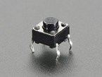
Some projects using the Raspberry Pi involves building circuits on breakout boards, at least when first prototyping the circuits. One component that is common in these circuits is the button switch, a push button that completes and breaks the circuit. The photo to the left is a button switch made for use on breakout boards. The four pins on the button fit into the holes on the breakout board and can span the center divide.
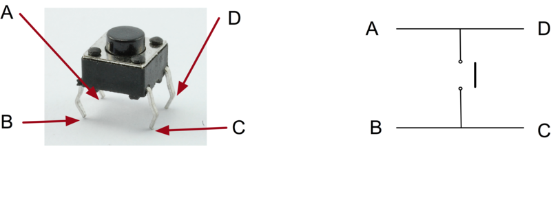
These buttons has two pins connected to both sides of the button. When the button is pressed, all four pins are connected and the current can flow through the switch. When the button is released, each pair of pins are connected to each other but not to the other pair. The photo below shows how the pins are wired in the switch.
Button Switch
Using a button switch is rather simple. One pair of pins, A/D or B/C, is connected to power side and the other pair of pins, B/C or A/D, is connected to a resister to ground and to a pin on the Raspberry Pi GPIO. When the button is released, the GPIO pin is pulled to ground, which is the LOW signal. Pressing the button results in the GPIO pin to Vcc also known as the HIGH signal.
In an ideal world, this is all that you need to do and the Raspberry Pi just has to check the state of the GPIO pin that the switch is connected to. A HIGH or LOW signal on the pin would tell the Raspberry Pi what state the button is in. You could also program the Raspberry Pi to generate an interrupt and a callback function when the button pin changes state. Unfortunately, we do not live in an ideal world.
Ideally, when a button is pushed, the voltage will smoothly rise and when the button is released the voltage smoothly falls back to zero. In a perfect, ideal world, the signal would form a square wave with leading and trailing edges raising and falling instantly. In the real world, the button will bounce when making and releasing contact. If plotted, this would look like a bunch of spikes instead of a smoothly raising and falling edge. This leads to the problem that the GPIO pin will see multiple HIGH and LOW signals each time the button is pushed and released. The trick then is to determine when the button is pushed and released without the false signals from the bounce. This is know as debouncing the button.
If you use the RPi.GPIO Python Library, you need to worry about debouncing the button switch. There are two ways to debounce the switch. The first is with software where you determine how long the bouncing takes. The software triggers on the first leading edge change detected, the signal raising or falling, then wait for the maximum amount of time that the switch is expected to bounce before checking the button state for the final results.
The software solution works though it requires that the software is delayed the bouncing time each time the button changes state. Sometimes a hardware solution is more practical. The deciding factor on which technique used should depend on how time critical the software is and the maximum bounce period that is expected.
To debounce a button switch with hardware involves adding a capacitor to the circuit on the GPIO side of the switch. The capacitor will dampen the bounce and turn it into a smoother rise and fall of the voltage when the button is pushed and release. There are multiple debounce circuits discussed on the Internet. The simplest uses a capacitor and a resister. More complex circuits use a single capacitor with multiple resisters. The more complex the debounce circuit is usually means the smoother the rise and fall of the signal is. The following links are for pages that have schematics and code for handling button switch debouncing.
Button Debouncing
-
A Guide to Debouncing
This PDF explains in detail the cause of bounce and circuits that can be used to debounce the circuit. The paper also provides the math that can be used to figure out the best component values to use for the capacitor and resisters and how to use NAND Gates for more sophisticated debounce circuits. -
Avoiding False Hits with RPi.GPIO Edge Detection
This is an article in the Raspberry Pi User Forums that deals with handling the bouncing signal when a button switch is pressed and released. The code makes use of the RPi.GPIO to access the pins on the GPIO. -
Debouncing a Button with Arduino
Sometimes when you press a button once, it registers as two or more presses. This page offers a solution for Arduino. The hardware solution also applies to other circuits including ones used with a Raspberry Pi computers. -
Debouncing Contacts - Part 2
From The Ganssle Group: Perfecting the Art of Building Embedded Systems website. The second page on A Guild to Debouncing, the part containing hardware and software solutions. The first page is about the problem of debouncing with empirical data. A link to the first page is available at the top of this page. -
Switch Debouncing
From The Lab Book Pages website, an article on switch debouncing. The page provides several different debounce circuits and logical code for using them. The logical code needs to be translated into a programming language such as Python or Java.