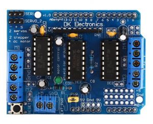
The robot chassis that I selected has four DC motors for the wheels. The Arduino UNO with the use of the L293D Motor Driver Shield has the capacity to control the DC motors. The reason that I am using the Arduino instead of the Raspberry Pi is that the motors run off of 5 volts. The Arduino bus is based on 5 volts while the Raspberry Pi is based on 3.3 volts. So basically, my choice is based on using the boards that require the least amount of fiddling with.
My choice for the Motor Driver Shield is the L293D which supports both four DC Motors and two servo motors. The shield also allows for external power to be supplied for driving the motors so that the current is not pulled from the Arduino. The servo motors are controlled directly from the Arduino, on pins 9 & 10. The documentation for the L293D states that the signal pins for Servo #1 is Pin 9 and Servo #2 is Pin 10. A quick test of my boards shows that this is reversed for the version of the L293D board that I bought.
The DC Motors connect to the blue connectors with screws on two opposite sides of the board; see photo below. These connectors do not connect directly to pins on the Arduino and thus need a special library to run them. The library that I plan to use is version 1 of the Adafruit AFMotor Library. There is a version 2 of this library. I am not sure if it works with this board or the newer motor driver board that Adafruit sells. I will probably see if both libraries work though version 1 should work with this board.
The photo above is from a different website than the one that I bought my L293D board. It looks identical from what I can tell. Some of the features of this board are:
- It plugs directly into the Arduino board.
- It has a reset button, lower left corner, that provides access to the one on the Arduino. With the shield plugged in, the reset button on the Arduino is basically not accessible.
- There are two 3 pin connectors, in the upper left corner, for plugging in servo motors.
- My robot will have at least one ultrasonic ranger finder sensor in the front of the vehicle that can be pointed in different direction by a servo motor.
- I am leaving the option open to place a second sensor in the rear of the vehicle. This will be a second phase improvement.
- The six analog pins on the Arduino are accessible on the L293D board.
- To use these pins, three pin headers of 6 pins will need to be soldered onto the board in the holds in the lower right corner of the board just above with the pins connect to the Arduino.
- These pins, A0-A5, can also be used as digital pins 14-19 on the Arduino. My hope is that I will be able to run the ultrasonic sensor with those pins.
- There are three sets of blue connectors with screws. The two with 5 connectors are where the motors connect to and the one with 2 connectors is for the external power supply.


