

Robotic Car Display
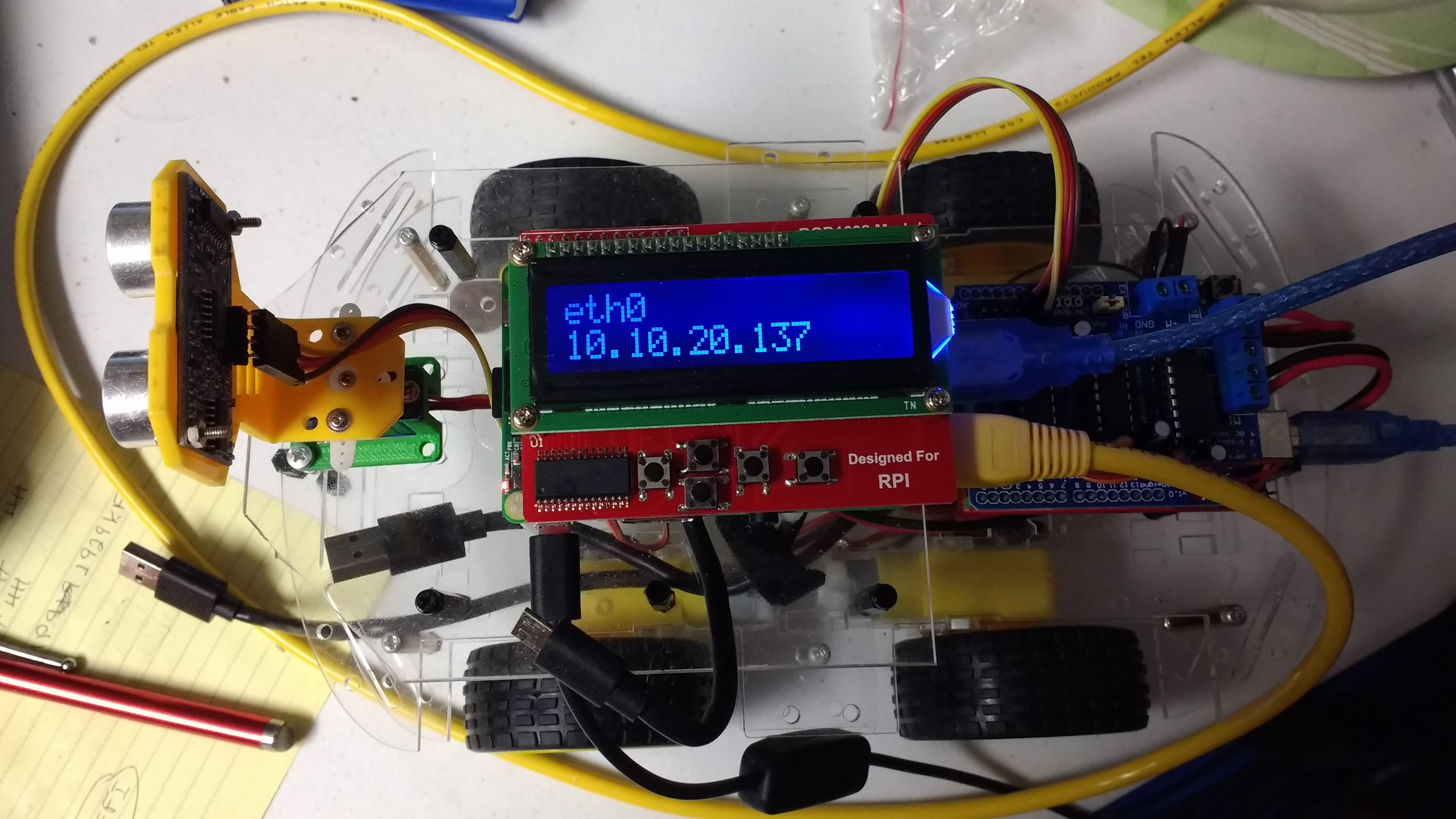
There was a robot car at a Robot Gathering in Roanoke that had an LCD display mounted on its Raspberry Pi. This display provided information such as the output from the Ultrasound Distance Sensor. This was an excellent idea and I decided to add one to my Robot Car.
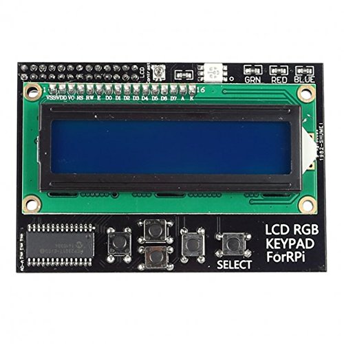
SainSmart I2C RGB LED with Keypad
Adding the LCD Display was not as easy as I assumed it would be. The first LCD Hat that I purchased is the SainSmart I2C IIC Interface RGB LED Screen LCD 1602 + Keypad For Raspberry Pi. I could not get this module to work on the Raspberry Pi. Neither the C/C++ examples using the WiringPI nor Java examples using PI4J would work.
One of the C programs worked once but did not work a second time. This showed that at least this piece of hardware works. I tried to get documentation for this module by writing to SainSmart. They never responded.
Googling for information showed me told me that this module is not standard as compared to the LCD Display with Keypad sold by Adafruit. This translates to the pin numbers are different. Most of the code examples require that you know the pins associated with the LCD data pins, the RS, RW and E pins.
On top of that, the RGB feature did not change the background of the LCD display. Instead it lit up an LED that is the white square at the top middle of the photo. This LED is bright enough that it is difficult to read the display when the LED is on.
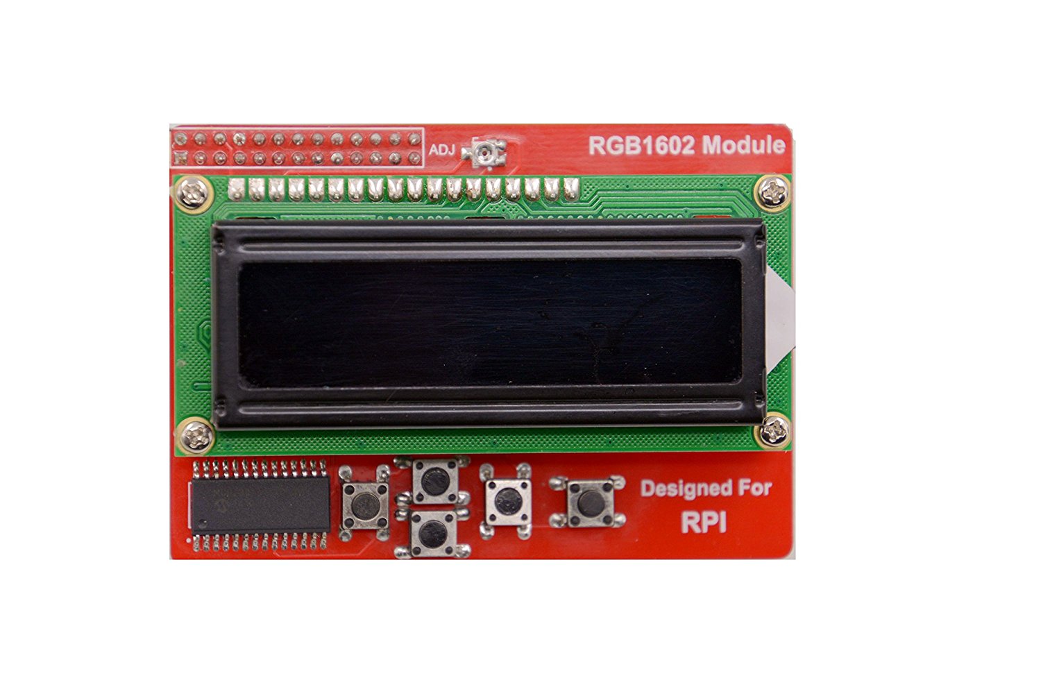
RGB LCD 1602 with Keypad
After more than a month of struggling without success, I decide to abandon the SainSmart LCD Display and purchased another. I still did not want to get the Adafruit LCD Display because of its price. I ended up getting the LCD Display shown in the photo on the right. It is not clear who manufactures this module. It is available from multiple vendors on Amazon.com. I found the best price on eBay.com.
Besides this module using a red board, it also has more pins on the LCD chip than the SainSmart LCD module. The pins are the silver solder on the green board that holds the LCD chip that is the LCD Display. These extra pins control the LED of the display Background, not an LED that blinds the user. An additional feature of the LCD Module that was not shown online is a rubber foot that sits over the Ethernet Connector of the Raspberry Pi. This foot prevents the LCD board from shorting out on the metal casing of the Ethernet Connector. This is catty-corner from the GPIO header and provides more support for the module when the buttons are being pressed.
The LCD Module is referred to as an RGB 1602 or 16×2. The RGB is for the 8 colors, including black and white, of the background colors. The 1602 or 16×2 are for the fact that the display is 16 character long and has 2 rows.
This module has online documentation and the link to it is listed on each webpage that sells the module:
Raspberry Pi RGB1602 LCD Module

RGB LCD 1602 with Keypad for Raspberry Pi.
This LCD module worked with the C/C++ example provided by the documentation. It still did not work with any of the Java examples. After weeks of failure, I finally started reverse engineering the C/C++ example that worked and the Java examples that did not. The problem was not with identifying the correct pin numbers. The pin numbers are different from the Adafruit version though they were available on the documentation.
The problem turned out to be due to the fact that the LCD modules use I2C to communicate with the LCD Chip. This includes this LCD Module, the SainSmart and the Adafruit modules. The problem with the Java code is that it attempts to send the code directly to the LCD Chip. Each of these boards contain an I/O Expander chip that handles the I2C communication on one side and communications with the LCD Chip on the other.
What was necessary was to write my own Java code that could talk to the I/O Expander chip and send data to the LCD Chip through the I/O chip. The documentation states that this module uses the MCP23017 chip for the I/O Expander and the HD44780U chip for the LCD. Links for documentation for these two chips is listed below.
The PI4J provides a class I2CDevice that handles the actual communication to the MCP23017 chip. I2C, also known as IIC, is for Inter-integrated Circuit Protocol. This protocol is designed for communications between different Integrated Circuits using only two data lines plus a common power and ground line. It is not necessary to fully understand this protocol, though a tutorial for I2C is in the links below. The key things that are needed is what I2C bus is being used and the slave address of the MCP23017. To determine this information use the command i2cdetect. Run the command ‘i2cdetect -y N’ where N is either 1 or 0. Zero works for older Raspberry Pi boards while one works for newer boards. The output is a matrix of addresses. Most will be 00. One of the non-zero values is the slave address of the MCP23017. This board with a Raspberry Pi 3 uses bus 1 and slave address 0x20.
The MCP23017 has a set of registers that need to be configured in order to use the I/O Expander chip to communication with the HD44780U (LCD Chip). The information for this setup can be found in the documentation of the MCP23017, link below. The MCP23017 has two 8 bit data or GPIO ports. GPIO A is connected to the HD44780U and GPIO B is connected to the 5 buttons.
The documentation for the LCD Module shows the 5 buttons in the schematic as switches 1 thru 5 and does not state which button is which on the board. Experimentation showed that the buttons are as follow:
- Select Button
- Right Button
- Down Button
- Up Button
- Left Button
Anyone interested in seeing the actual source code, ask by commenting on this post.
Links related to the LCD Hat
-
HD44780U (LCD-II) - Dot Matrix Liquid Crystal Display Controller/Driver
Documentation for the LCD Display Chip. -
I2C Tutorial
In this tutorial, you will learn all about the I2C communication protocol, why you would want to use it, and how it’s implemented. The Inter-integrated Circuit (I2C) Protocol is a protocol intended to allow multiple “slave” digital integrated circuits (“chips”) to communicate with one or more “master” chips. Like the Serial Peripheral Interface (SPI), it is only intended for short distance communications within a single device. Like Asynchronous Serial Interfaces (such as RS-232 or UARTs), it only requires two signal wires to exchange information. -
MCP23017/MCP23S17 - 16-Bit I/O Expander with Serial Interface
Documentation for the MCP23x17 chip used to communicate with the LCD Chip. -
Raspberry Pi RGB1602 LCD Module
Documentation for the LCD RGB 1602 Display with Keypad for Raspberry Pi. This Raspberry Pi Hat uses I2C to minimize the number of GPIO pins used. Two pins are used for the I2C communcation, Two pins for power and ground and three pins to control the LED Background colors.
Hi,Could you share me the code of the RGB1602 module?
Yes, give me a couple of days to get it into Github and I will post the information needed to download it.
Hi fbi007130,
See comment below for accessing the LCDDisplay source code that I wrote. I hope it will still be useful to you.
Hi fbi007130,
I apologize for taking much longer than expected, getting my code into GitHub so that it is available for others to use. I had some problems with the creation and loading of the repository. Those problems have been resolved.
The source code is now available in the git repository listed at https://github.com/sflebrun/RobotCar and is under the RaspberryPi/LCDDisplay subfolder.