

I originally thought that mounting the Raspberry Pi and the SG90 servo motor for the ultrasound distance sensor would be a simple task. There were plenty of holes already in the two platforms that came with the robot chassis. I was wrong. The robot chassis was designed for an Arduino UNO board. There were holes for the Arduino. None of the other holes, which there were many to choose from, matched up with the standoff holes on the Raspberry Pi nor the SG90 mount.
My original plan was to mount the Arduino on the bottom platform leaving me plenty of room on top platform for the Raspberry Pi and the servo motor. The Arduino did not fit on the lower platform. It was a couple of millimeters too tall and thus prevented the top platform from attaching with the standoffs provided by the robotic chassis. I had two options. One option was to drill more holes in the top platform and mount both the Arduino and Raspberry Pi on the top platform and squeeze the servo motor on there too. The second option was to make a third platform that would mount on the top platform and mount the Raspberry Pi and servo motor to the third platform.
The first option was the simplest though it would require the removal of all the components already attached. Mainly, the Arduino board with its motor driver shield and all the wires from the motors that connected to the shield. I went with the second option mostly because I did not want to undo the wiring already in place and because I have never worked with acrylic sheets. This project is after all a learning experience.
Third Platform Pattern
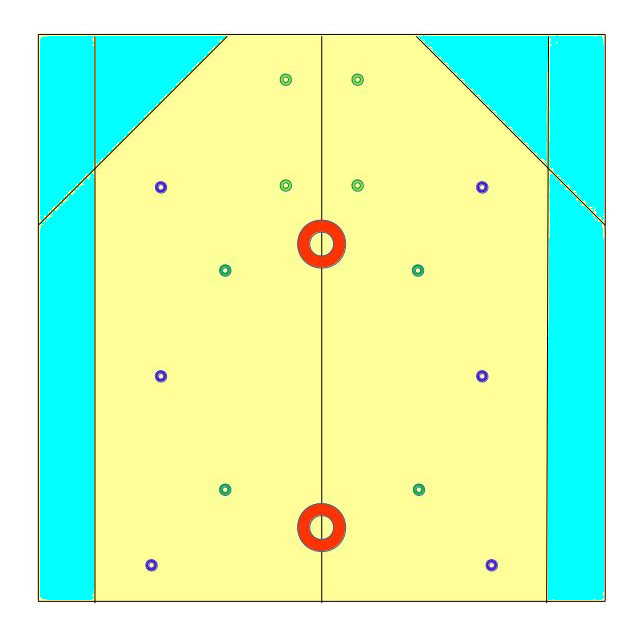
The first step was to design the platform. What shape and what size should it be. Using LibreOffice Draw as my “CAD” tool”, I drew out the platform that I wanted to scale. An image of the platform is to the left. It starts with a 15 cm x 15 cm sheet of acrylic. And ends with a sheet that is basically 12 cm x 15 cm in size. The cyan/blue sections are to be removed and the circles represents where holes need to be drilled.
The actual size of the acrylic sheet that I started with was 8 x 10 x 0.08 inches which is 20.3 cm x 25.4 cm x 2 mm and cut it down to a 12 cm x 15 cm rectangle and then broke off the two diagonal sections in the front for looks. My first thoughts was that the third platform would be 15 cm wide instead of 12 cm. Holding the pattern above the robot chassis showed me that my original design was too wide and that I could trim off 3 cm without impacting my mounting holes.
The choice of thickness for the acrylic sheet came down to what was available. I was looking for something close to 1/8 inch or 3 mm to match the two platforms that came with the robot chassis. What I found was the 0.08 inch or 2 mm thick sheets at a reasonable price. The stiffness of the 2 mm thick sheet seemed strong enough for my usage so 2 mm was what I ended up going with.
Cutting straight edges on acrylic sheets is relatively easy. All you need is a solid straight edge, a knife for scoring the sheet, and a solid edge for applying pressure for snapping the acrylic. There is a Lowes a few miles from my house so I purchased my acrylic sheet and tools there. The acrylic sheet and cutting knife are listed below in the tools and parts list below. They are available from other brick and mortar stores as well as online stores so shop for the best prices and convince.
My acrylic cutting when well for the most part. The long straight edges came out cleanly. One of the diagonal cuts was a bit messy. I should have scored that cut more before attempting to break it. The unevenness of that break was minor and I felt there was no need to try to fix it.
The robot chassis came with M3 standoffs also called spacers. The Arduino also used M3 standoffs. Therefore, the mounting holes were drilled with an 1/8 split point bit leaving 3.2 mm diameter holes. The 6 blue holes, 3 on each side, are the holes needed to attach the third platform to the top platform. Note that the bottom two blue holes are slightly wider apart the the top and middle holes. This was based on hole positions on the robotic chassis platforms. The 4 dark green holes at the back end of the platform, inside the blue holes, are the holes for mounting the Raspberry Pi. The 4 lighter green holes at the front are for the servo motor mount. The two large red holes, placed along the center line, are holes for wires to pass through. These 2 holes are not to scale. I ended up using a 3/8 inch wood drill to make those holes, starting with an 1/8 hole in the center of each as a guide hole.
Each of the holes were made with a hand drill. I marked each hole by poking a thumb tack through the pattern, marking the spot with an ink pen and then drilling the holes. The acrylic was clamped to a 2×4 board for support. Most of the holes ended up where they should have been. The back two holes for the servo motor mount were off. The servo motor should not be under much torque so it is mounted using the front 2 holes only. If this does not work, I will have to start over and make a new third platform. I am not sure if my holes were off because of the pattern or because I used a hand drill instead of a drill press.
Note, I used part of the left over acrylic sheet to practice drilling holes. It turns out that with the split point bit, I did not have to use any lubricant. The bit drilled through the sheet cleanly. The bit did bind up a few times. When that happened, I had to work the bit out, clean the acrylic threads stuck to the bit before continuing to drill the holes. The 2 wire holes started with 1/8 holes and then applying the wood bit. The 1/8 inch holes guided the wider flat bit in. Again, practice on scrape pieces of acrylic to make sure that your wood bits work on acrylic.

Top view of robotic car with third platform.
After mounting the servo motor, I discovered my other mistake. The Raspberry Pi holes for the standoff are not big enough for M3 standoffs. Instead of being 3 mm holes like the Arduino, the holes in the Raspberry Pi board are 2.75 mm. I should have realized this before drilling the holes since I was working with the Pi board schematics for placing the holes. ( Raspberry Pi B - Board Schematic ). Not a disaster, at least the holes lined up with the Raspberry Pi. The fix was to get the right size standoffs.
My initial web search resulted in M3 and M2 standoff kits. I had the M3 standoff kit which I used for the Arduino board so I ordered the M2. The M2 has 2 mm diameter threads so they should work in the 2.75 mm holes, right? Wrong. While the M2 did work on two of the 3.2 mm holes, they fell through the other two holes. The diameter of the widest part of the M2 standoff post is about 3 mm. In the picture to the right, the M2 standoffs are holding the Raspberry Pi in place. It probably will not take much of a jolt to cause two of the standoffs to fail. Another Internet search and a set of M2.5 standoffs are on the way. It is a better bet that these standoffs will work since they were labeled M2.5 for Raspberry Pi. I guess I should have expected the hole sizes to be different between the Arduino and the Raspberry Pi. After all, the Arduino works on 5V and the Raspberry Pi on 3.3V.
The second photo, the one to the left, shows the robotic car with the third platform installed and the Raspberry Pi and servo motor mounted. There will be more information on what the robotic car looks like with the third platform in my next post.