

Robotic Car
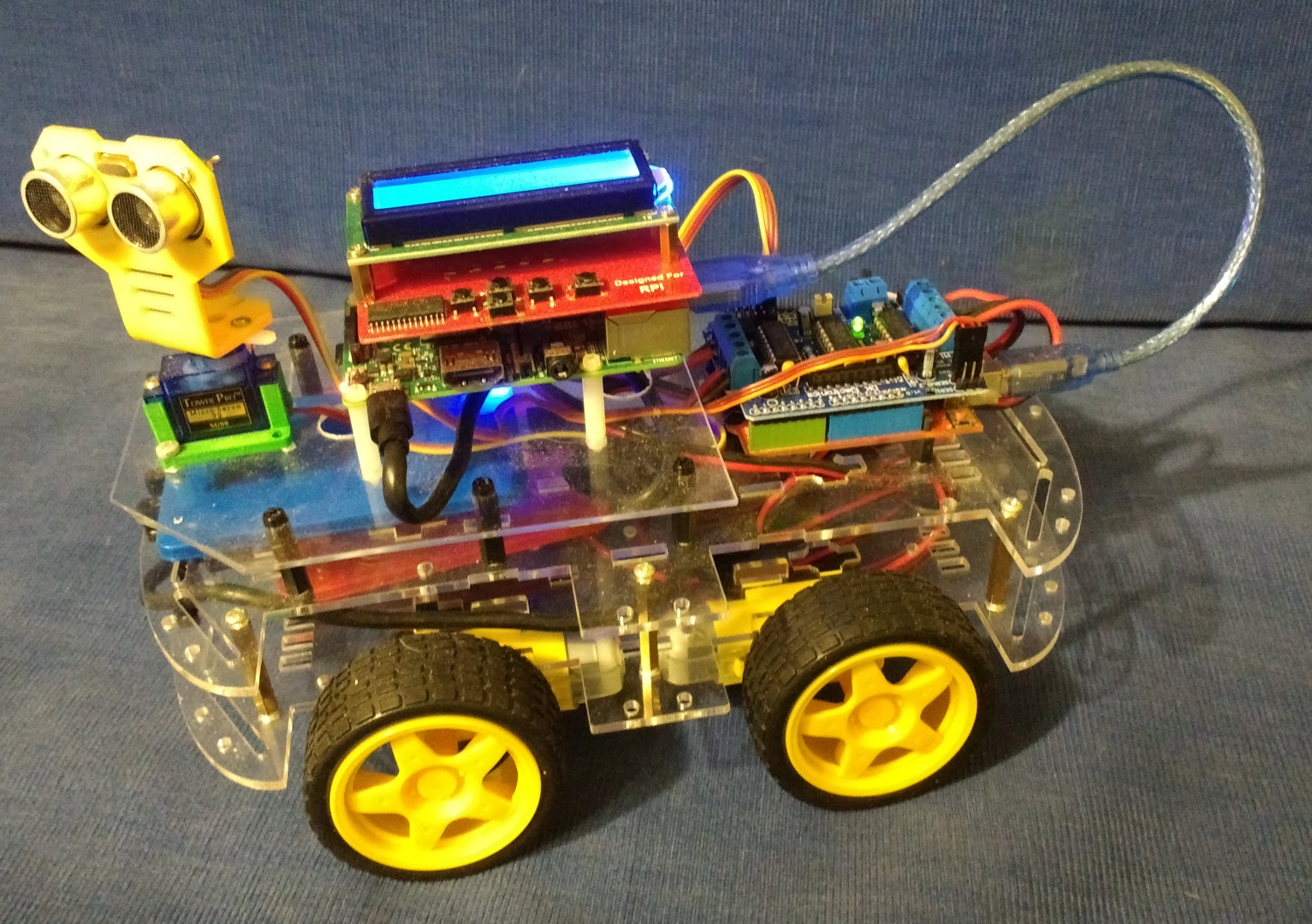
It has been a while since my last post. Work is progressing though a bit slower that I had originally planned. The title photo for this entry is the Robotic Car with all components installed. At least, all that were planned.
The coding for the Arduino is complete. It can process all the commands necessary to run the car. All motors work; four to drive the wheels and a servo motor to turn the ultrasound distance sensor. The ultrasound sensor can be run by the commands sent to the Arduino with the results being sent back to the Raspberry Pi.
Coding the Command Center on the Raspberry Pi is taking more time than originally expected. The problem that I am running into is that there needs to be a fairly accurate intervals between commands. For instance, when you are trying to turn the car, you want the wheels on each side to turn at different rates. This is already possible with the command being sent. You want the command to start the turn and end the turn to be sent at different times to control the amount of the turn. The Java VM is notorious for being bad for doing any real-time timing. Garbage Collection could kick in in the middle of your wait and throw the timing off.
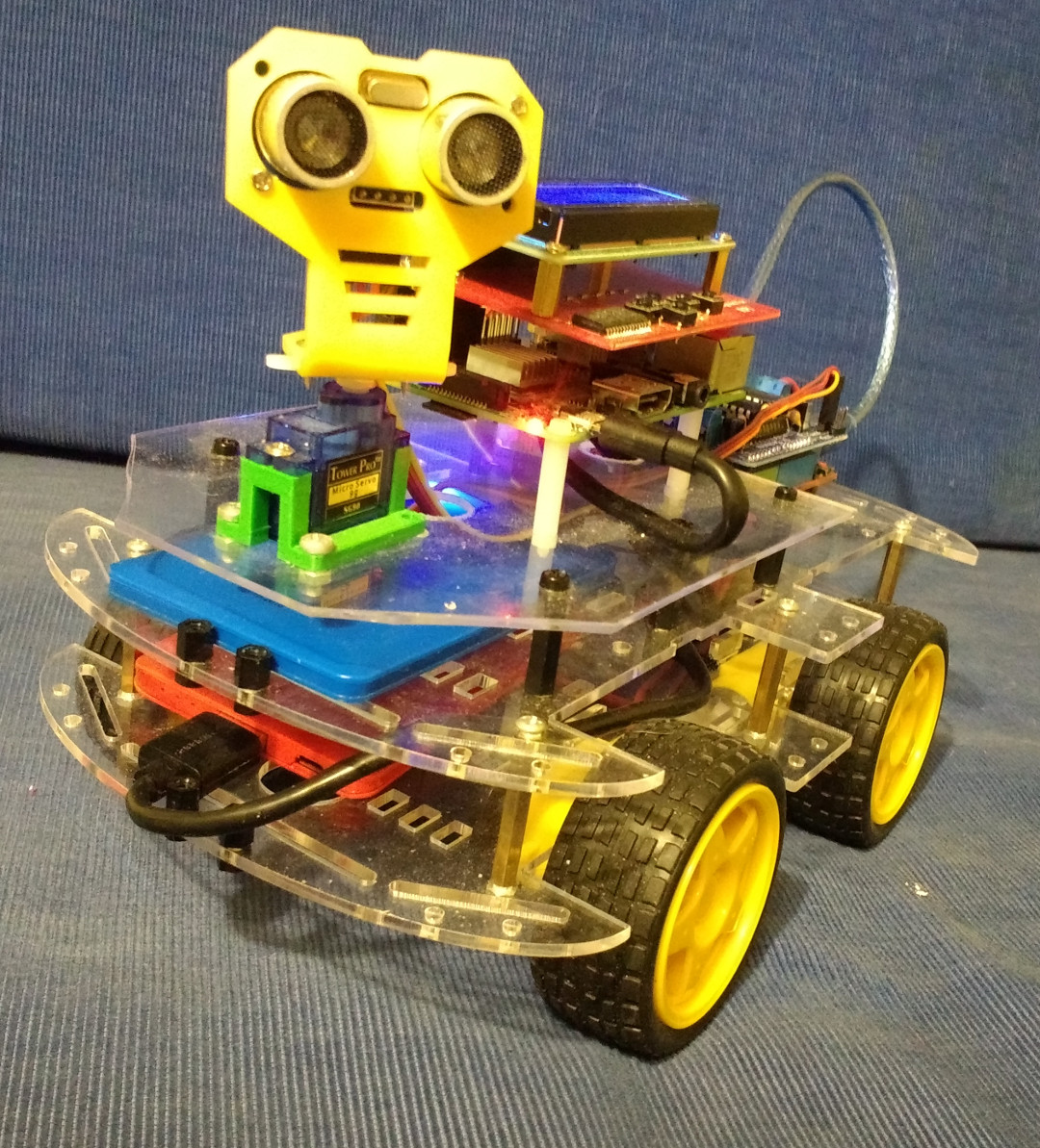
Robotic Car
I have temporarily put a hold on the Robotic Car development while a wait for a new component to arrive. I have order a timing or clock board for the Robotic Car. It is coming from China and the amount of time between shipping and arrival makes me think it is coming on a slow boat. The clock board is due to arrive any time over the next three weeks. Once it arrives, I will want to write some code to see what I can do with it. If it solves my timing issues, the next steps will be to figure out how/where to mount the board on the car and how to connect the board to the Raspberry Pi GPIO.
In the car’s current configuration, the LCD and key board is plugged into the GPIO leaving no direct access to the GPIO pins. The clock board communicates to the Raspberry Pi over the I2C pins, just like the LCD display. So, I will either have to figure out how to get the clock to connect to the second set of I2C pins or share the ones used by the LCD display. I2C protocol allows for multiple slave devices to be connected to the same set of I2C pins. Each slave device has its own unique address that allows the master, the Raspberry Pi, to control which device it is sending to and receiving from.
One option will be to solder wires to the LCD pins that connect to the CPIO pins and connect those wires to the clock board. I am not thrilled with this option because I prefer to keep each component easily replaceable. The second option is to get another hat for the Raspberry Pi that allows multiple devices to have access to the GPIO pins. This option has the drawbacks of requiring another component which is not expensive and then figuring out how to mount the LCD Display so that it is secure on top of the middle board. I will be doing some research to find out if there is a third option available.