

Today, the assembly of my robotic car started. The motor and wheels were attached to the platform.
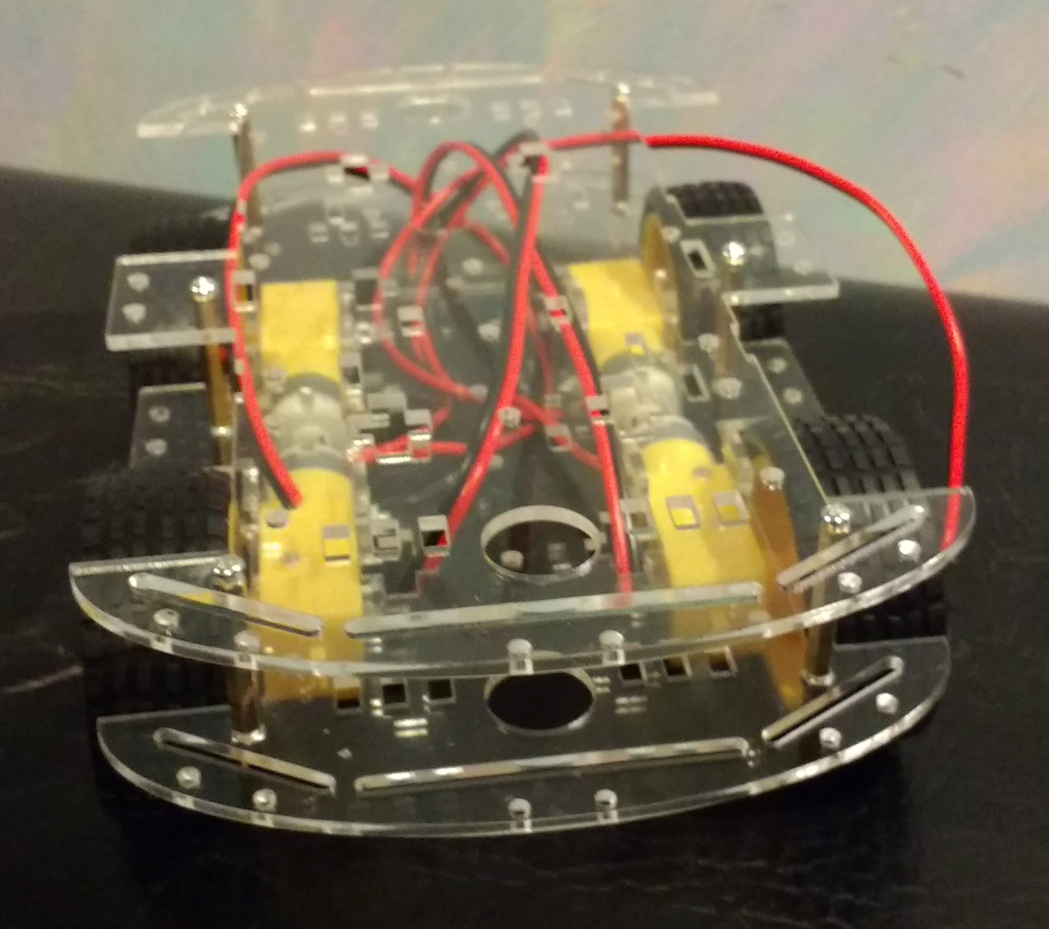
Assembled Robot Chassis – Front
My first mistake became obvious when I tried to solder wires onto the DC motors. I purchased wires of a gauge too big for the connectors on the motors. 18 gauge wire is too big to fit into the small holes on the motor.
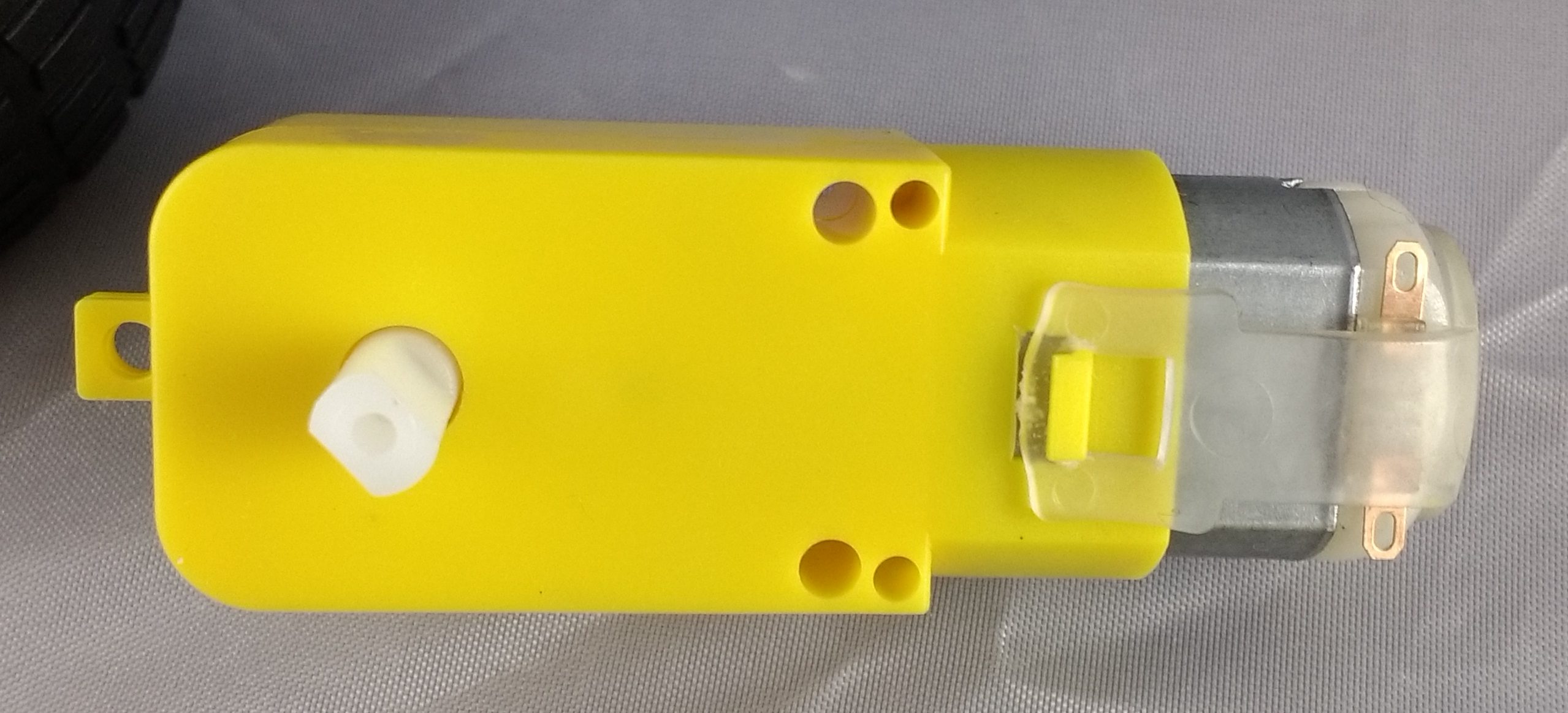
DC Motor for Robotic Chassis
Luckily, the wire was not a solid wire and is composed of multiple strands. My solution, instead of buying more wire, was to separate the strands into two subsets, pass one bundled through the solder point on the motor and twist the two bundles back together on the other side before soldering. Not a perfect solution though it should work. The power supply that will be powering the motors is a 5 V/2.1 A source. The wire and the solder should be sufficient to handle the load.
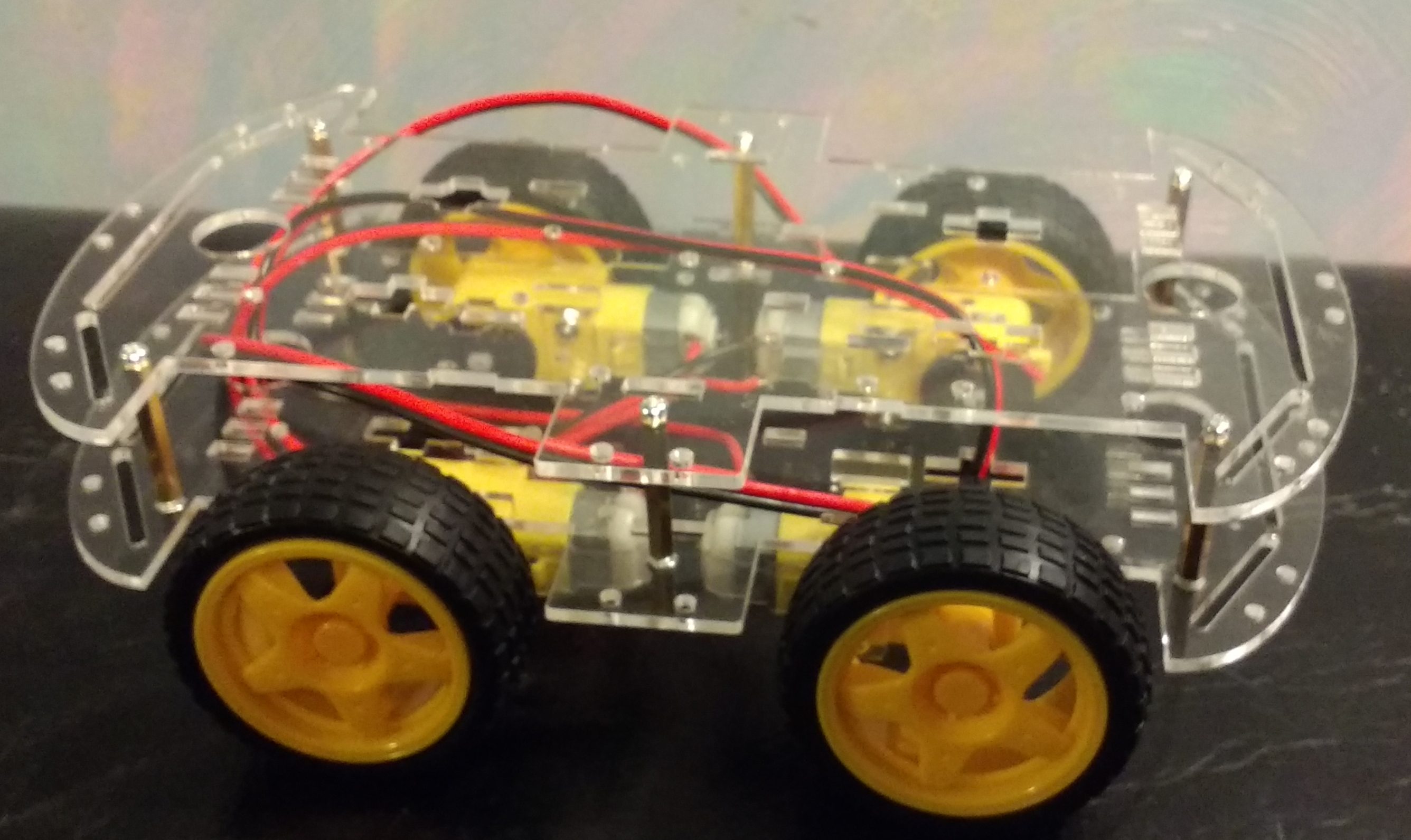
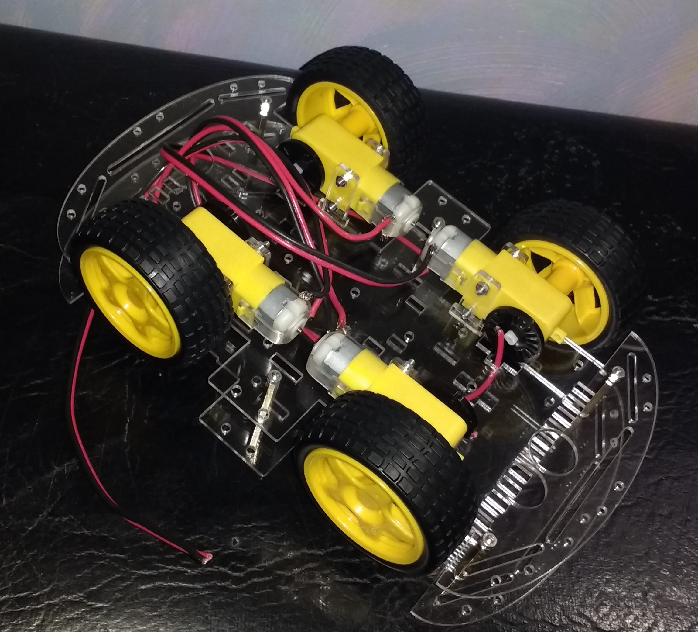
Assembled Robot Chassis – Side
The side view, shown above, lets you see the wheels in the upside down position. If the bottom platform was flipped over as the original specifications have it, the wheels would extend just above the top platform. In my version, the platform ride higher with the wheels only beside the lower platform. In my setup, the motors and wires are exposed to the ground. The original design have the motors and wires protected by being above the platform. Since my robotic vehicle is intended to run on smooth surfaces such as tile and hardwood floors, this extra exposure of the wires should not be an issue. The wires will be fixed to the bottom of the platform so that they are not handing or dragging.
Assembled Robot Chassis – Top
The top and bottom views provide a clearer view of the motors. On the inside of each motor, opposite of the wheels, are black disks with many slots cut in them. These disks are held on only by friction with the axis. There is a screw hole at the end of the axis but no screws came with the chassis kit. As far as I can tell, these inner disks server no useful purpose. If anyone knows what they are for, please let me know in a comment. It is is possible that you could add a sensor that counts each slot as it goes by, thus determining the spin speed of the wheels. I have seen nothing online for that type of sensor.
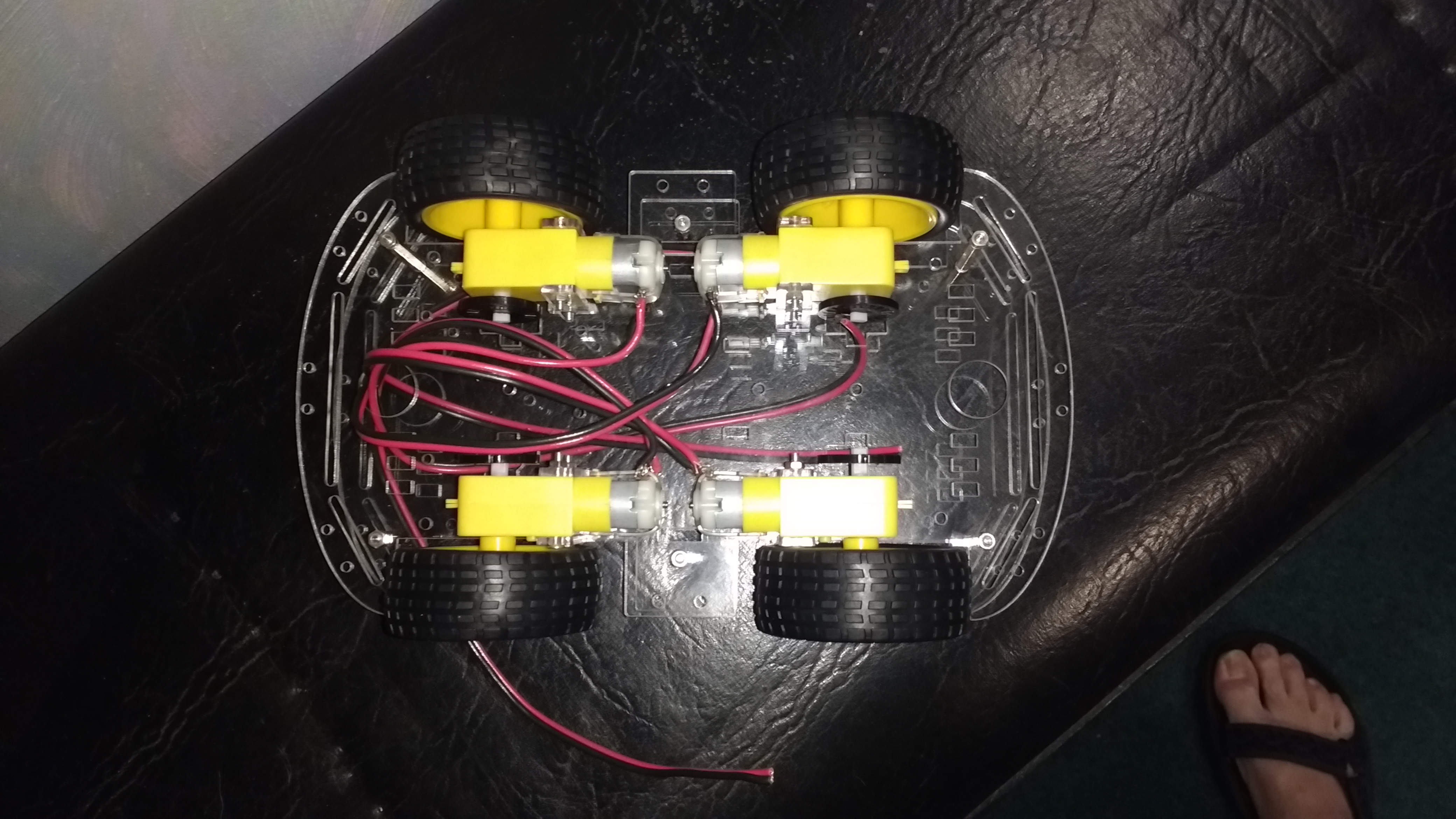
Assembled Robot Chassis – Bottom
The motors are fixed to the platform with two small plastic T shaped mounts made of plastic, of the same material as the platforms themselves. One of the mounts fits into a slot in the platform wide enough for all but the top of the T. The other mount rests in a notch on the edge of the platform. Two bolts pass through one mount, the motor and the other mount to secure the motor and mounts to the platform. The motor mounts are basically held in place by squeezing them together around the slot and the outer edge of the platform.
The reason that I flipped the bottom platform is so that there will be room for the Arduino on the top of the lower platform. The motors are too close together, not leaving enough room for the Arduino. The motors are under the platform since they are more durable than the Arduino board and its motor driver shield.
The power supply is also going somewhere between the platforms. Hopefully, there will be enough room on the bottom platform to mount it behind the Arduino. The power supply that I selected is a rechargeable power bank with two USB ports. Each port supply 5 volts at up to 2.1 amps. One USB port will power the motors and the other will power the Raspberry Pi 3. The Raspberry Pi, in turn, will supply the power to the Arduino board. There will be more information on the power supply in another post.